Scattering Waves
By Geno Cathy IV
Left Hand Circularly Polarized Truncated Patch Antenna Research
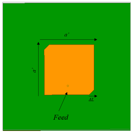
A left hand circularly polarized single truncated patch antenna was designed for 2 GHz operations. This design used an FR-4 substrate with a relative permittivity of 4.4, and had a thickness of 1.6 mm. Left hand circular polarization was realized by perturbing the top left and top right corners of the patch. Removing opposite corners produces a more inductive impedance across the two truncated corners which causes the electric field to have a phase 45\(^\circ\) compared with the -45\(^\circ\) of the electric field with the capacitive impedance across the two untruncated corners [4]. The length that needs to be removed from each corner is found by using this equation: \(\Delta L = \frac{a'}{\sqrt{Q_0}}\). Where \(a'\) is the length of of the patch antenna and \(Q_0\) corresponds to the orthogonally polarized modes with first-order approximations, which was varied to find the best axial ratio. \(Q_0\) is an estimated value as a function of substrate height [4]. The design of the LHCP single truncated patch antenna can be seen below:
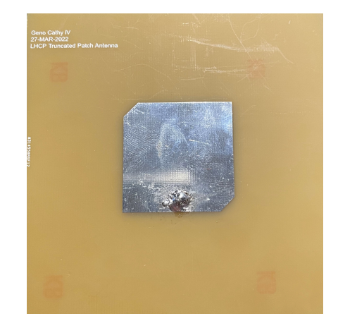
Once the antenna was fabricated, which can be seen in the image below the reflection coefficient was measured. The measured and simulated results were compared and plotted together. The \(|S_{11}|\) results can be seen next to the fabricated antenna image.(Zoom in to see a more clear image of the graph.)
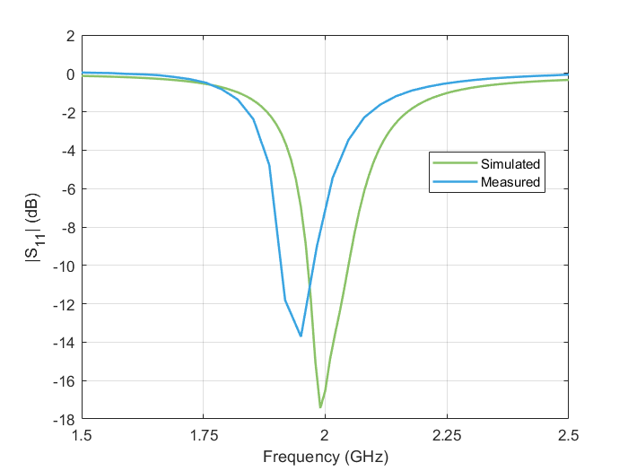
Compared to the simulations, the measured results show that the resonant frequency shifted slightly from 2.0 GHz to 1.95 GHz. Specifically the measured results indicate the minimum reflection coefficient is -13.7 dB at 1.95 GHz and the simulated results show the resonant frequency is -16.5 dB at 2.0 GHz. The frequency shift could be due to the simulation setup. The antenna was simulated using a perfect electric conductor instead of copper. Another factor for the shift in frequency is not having an accurate value for the relative permittivity of the FR4, since the manufacturer provides a range of relative permittivities for their FR4 material. Next, the axial ratio was measured. The axial ratio is the ratio of the major axis of the polarization ellipse to the minor axis [11]. A circularly polarized field is made up of two orthogonal electric fields of equal amplitudes and 90◦ out of phase. The goal of the axial ratio is to be under 3 dB for relatively pure circular polarization. The measured and simulated results can be seen below.
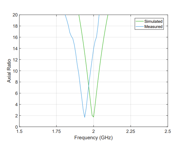
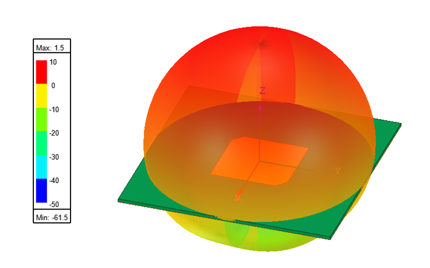
which indicates an axial ratio of 1.74 dB and 1.68 dB at 2 GHz, respectively. The measured results produce a very similar axial ratio and a shift in operating frequency from 2.0 GHz to 1.94 GHz. The LHCP single truncated patch antenna’s simulated realized gain was found to be 1.5 dBic.The 3D radiation pattern of the realized gain can be seen below.