2 GHz Reconfigurable Parasitic Patch Antenna
The motivation to design a radiation pattern reconfigurable antenna comes from the advantages of being able to dynamically reconfigure the radiation pattern in order to increase the signal to noise ratio and reduce multipath. The inspiration
for the reconfigurable antenna came from an IEEE research paper that designed a reconfigurable microstrip rectangular parasitic array antenna [1]. The linearly polarized reconfigurable antenna was designed using an FR-4 substrate with a height of 3.2 mm and a
relative permittivity of 4.4. The FR-4 substrate was chosen to lower costs due to the increased cost of a thicker board. The design utilized HFSS and consisted of one center patch and two parasitic patches on either side, as shown below:
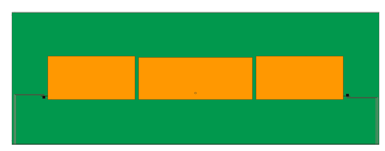
The first step in designing the reconfigurable antenna was to design the driven patch along with the two parasitic patches. Once the three patches were designed, many optimizations were run on HFSS to find the best positions and size of the parasitic patches, along with
the separation between the parasitic patches and driven patch. The best results for the reconfigurable antenna was found when the substrate had a height of 3.2 mm. Two RF single pole single throw (SPST), switches designed by Skyworks were used on both the left and right parasitic
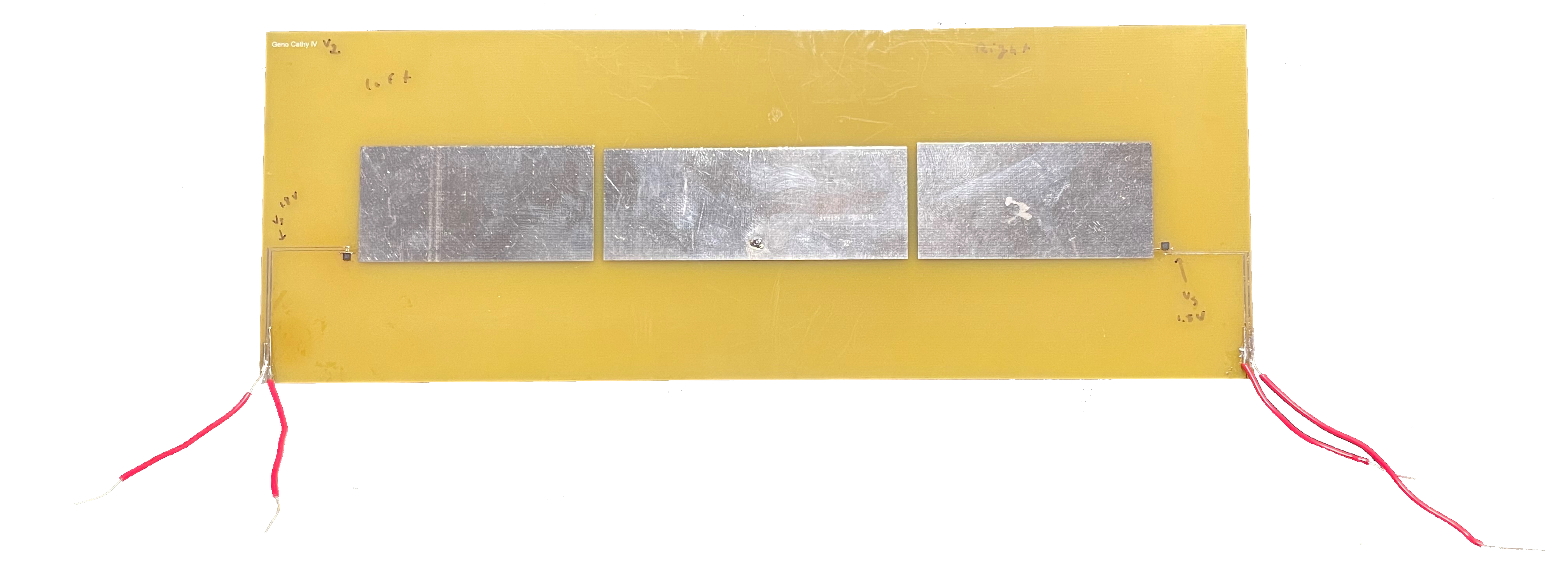
patches for reconfigurability. The fabricated antenna can be seen below:
The reconfigurable antenna simulations used lumped RLC components to model the RF switch along with the DC bias lines. The reconfigurable antenna was then simulated and all four possible different modes were evaluated. For all four modes, the reflection coefficient needed to be
under -10 dB in order to be considered an acceptable radiating antenna due to the reflected power being less than 10%. All four modes produce a reflection coefficient under -10 dB at 2 GHz. The simulated and measured reflection coefficient for all four states can be seen below:
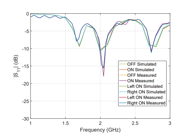
2 shows when both switches are in either the OFF state or ON state produce the same reflection coefficient for both simulated and measured results. The measured results produce a better reflection coefficient of -17.9 dB at 2 GHz while the simulated results produce a reflection
coefficient of -10.4 dB at 2 GHz. When the left switch is ON the simulated results show a reflection coefficient of -10.4 dB at 2 GHz and the measured results show a reflection coefficient of -15.6 dB at 2 GHz. When the right switch is ON, the simulated results show a reflection
coefficient of -11 dB at 2 GHz, while measured results show a reflection coefficient of -14.6 dB at 2 GHz. Both left and right ON states indicate that the measured results produce better results than the simulated results. The radiation pattern reconfigurable antenna can produce
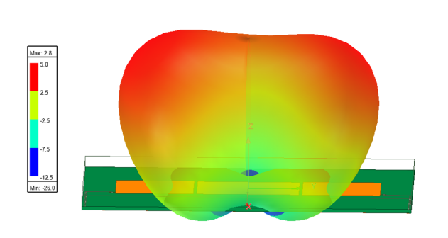
four modes with the different states of the switches. For the first mode, the RF switches are both in the OFF state, which produces a bi-modal radiation pattern with main lobes at -30◦ and +30◦ with a gain of 2.9 dBi in each lobe. The 3-D radiation pattern can be seen below:
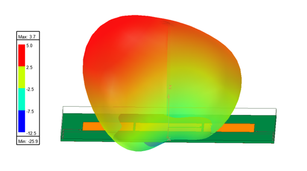
For the second mode, the left RF switch is in the ON state while the right RF switch is in the OFF state. This produces a -30◦ radiation pattern shift with a realized gain of 3.2 dBi. The 3-D radiation pattern and can be seen below:
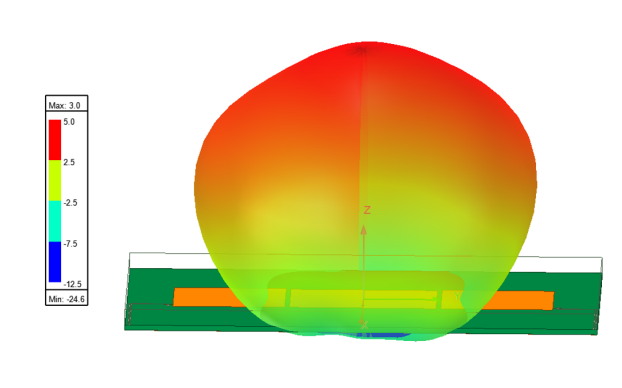
For the third mode, the right RF switch is in the ON state, while the left RF switch is in the OFF state. This produces a +30◦ radiation pattern shift, which is the mirror of the figure above. The figure below shows the fourth mode where both RF switches are in the ON state,
which produces a directive radiation pattern at 0◦ and a gain of 3.3 dBi.
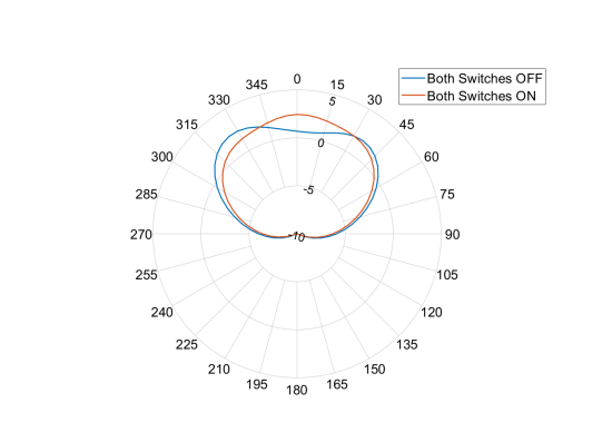
Moreover, the next figure below shows the 2-D polar plots of the case when both switches are in the ON state and when both switches are in the OFF state.
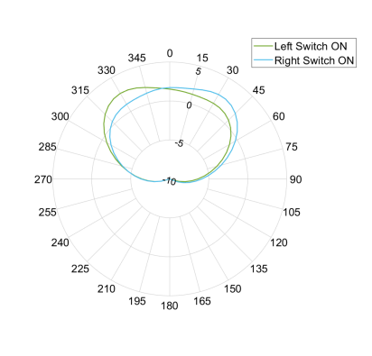
The next figure shows the 2-D polar plots of the case when the left switch is in the ON state (right OFF) and when the right switch is in the ON state (left OFF).