Scattering Waves
By Geno Cathy IV
Left Hand Circularly Polarized Truncated Patch Antenna Array Research
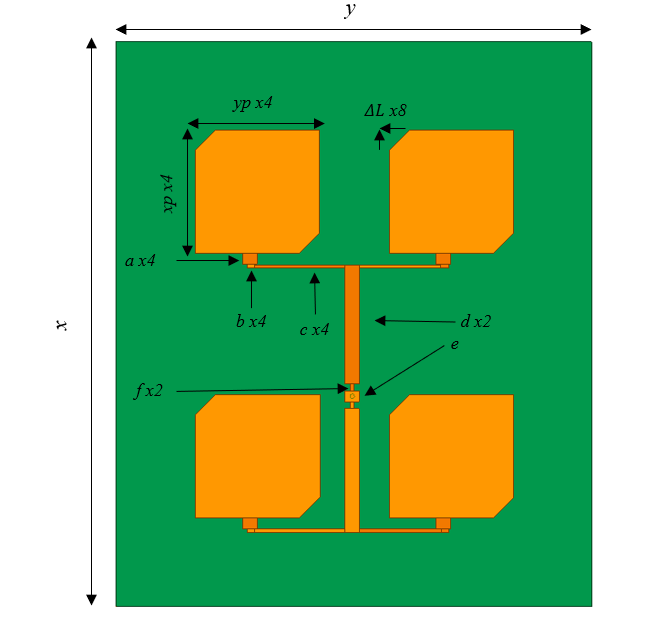
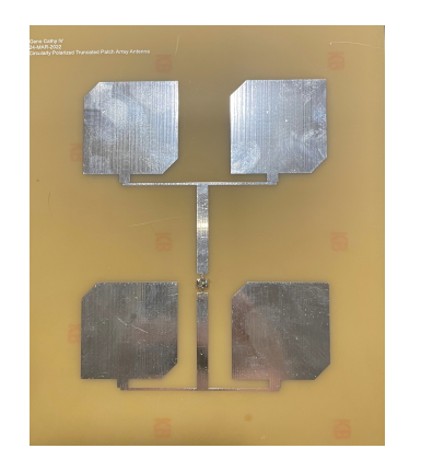
The antenna array consisted of four LHCP truncated patches that were impedance matched using a quarter-wave transmission line and fed in-phase. The truncated patches also used an FR4 substrate with a relative permittivity of 4.4 and height of 1.6 mm. The characteristic impedance of the quarter-wave transmission line \(Z_0\) was determined by: \(Z_{in} = \frac{Z_0^2}{Z_L}\) where Zin is equal to the input impedance and ZL is equal to the load impedance. Re-writing this equation gives (17), where the characteristic impedance equals the square root of the load impedance times the desired input impedance. \(Z_0 = \sqrt{{Z_L}{Z_{in}}}\) The design of the LHCP truncated patch antenna array in HFSS can be seen below along with the fabricated design:
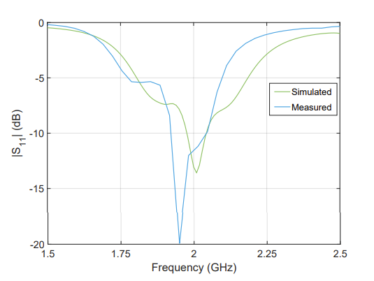
The simulated LHCP antenna array from HFSS produced an input reflection coefficient of -13.70 dB at 2 GHz, and the measured LHCP antenna array produced an input reflection coefficient of -11.56 dB at 2 GHz. It is worth noting that at a frequency of 1.95 GHz the input reflection coefficient would be -19.91 dB. This frequency shift is similar to the measured LHCP single truncated patch which had an input reflection coefficient of -13.70 dB at 1.95 GHz. These results can be seen below: